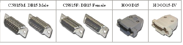
Electric part- H0Electrical connections between modules should be made with the following connectors:
To avoid larger quantities of components and reduce the possibility for more mistakes, and not least the economy and security of the module is fitted with two cable connectors are enclosed in plastic caps and placed in length 25 cm outside the length of the module. They hang the cables themselves, giving a total length between two modules of about 50 cm cables are firmly attached inside the bottom of the corresponding forehead, just between the edge of the base and carry openings..
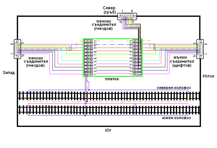
Table for cabling of modules:
Prevail mostly table that describes the relationship! !!! Typical NEM requirement is rails in a module to be at least two places connected to the electric system. This ensures the performance of the route, whether they are oxidized, suspended etc:
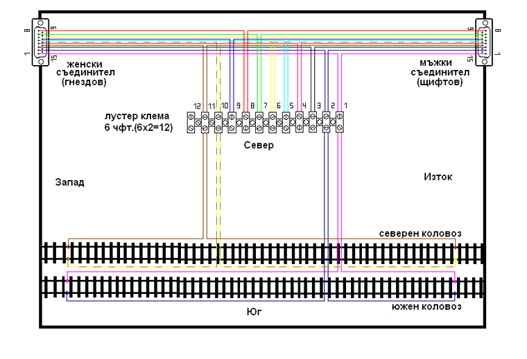
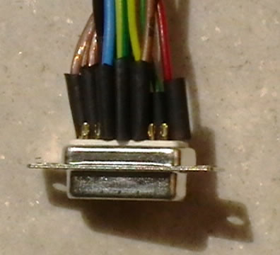
Reserved pin (E.g empty one) Is № 12 , Not №1 !!!
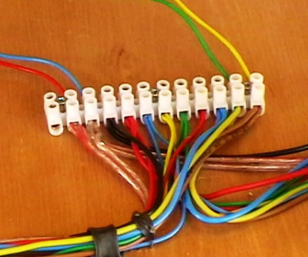
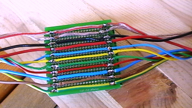
The final option is with wiring the 11 lines and 4 free pin are left as the reserve or additions. All welded wire must be insulated:
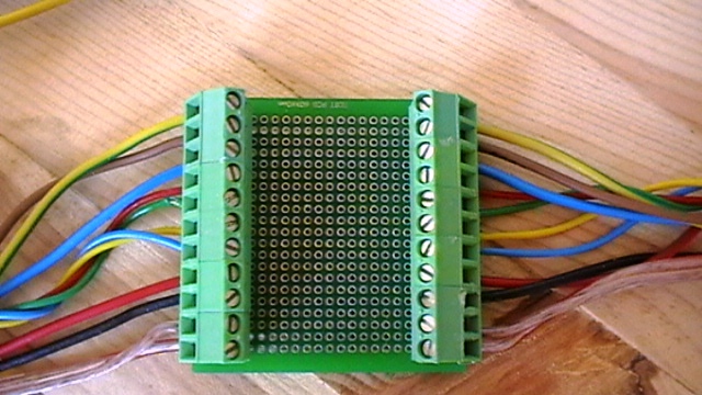
The second method for electrical connection inside the module.
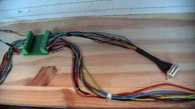
Used so-called "trial" and the quantity of PCB terminals with a total order to № 11. There is no spare terminal, but it is not necessary for options on the board:
Wiring is simple and clear, as is observed order of the numbers that match those of the luster terminal.
|